
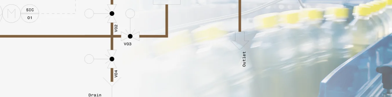
Piping & Instrumentation
The P&ID (Piping & Instrumentation Diagrams) discipline enables process engineers and designers to easily create piping and instrumentation diagrams (P&ID). Thanks to the intelligent linking of measuring points and devices with the schematics and plans of other disciplines, their interactions can be presented logically and checked. Plans in DXF or DWG format are read, augmented with intelligence, and “brought to life”. The unique and sequential numbering of the measuring points allows errors in a system to be quickly localized and fixed. The links between measuring point numbers and resources can be subsequently evaluated for the creation of measuring point labels and lists.
Due to the cross-disciplinary and uniform use of symbols from a central database, temperature or fill level indicators created in flow diagrams, for example, can be directly used again in the schematics. Changes are automatically applied across all disciplines. This increases transparency, prevents errors and saves a significant amount of time
Performance Focus
- Creation of P&ID schemes
- Linkage of P&ID measuring points with objects in other disciplines
- Linkage of measuring point numbers with symbols
- Display of measuring point numbers in the symbols
- Import/export of measuring point numbers
- Automatic numbering of measuring points
- Overview of resources used with measuring points
- Quick navigation between components of measuring points via the Measuring Point Manager
- Searching/Replacing in the Measuring Point Browser
- Sorting in the Measuring Point Browser
Technology at a glance
- Symbols as per DIN 10628-1
- Various media lines as per DIN 2403
- Conversion of measuring points from DXF/DWG format to logical elements (measuring points)